Pošaljite poruku
Ako ste zainteresovani za naše proizvode i želite da saznate više detalja, ostavite poruku ovde, odgovorićemo vam u najkraćem roku.

Како ради ватрогасна пумпа? Објашњен принцип рада пумпе на ватрогасном возилу
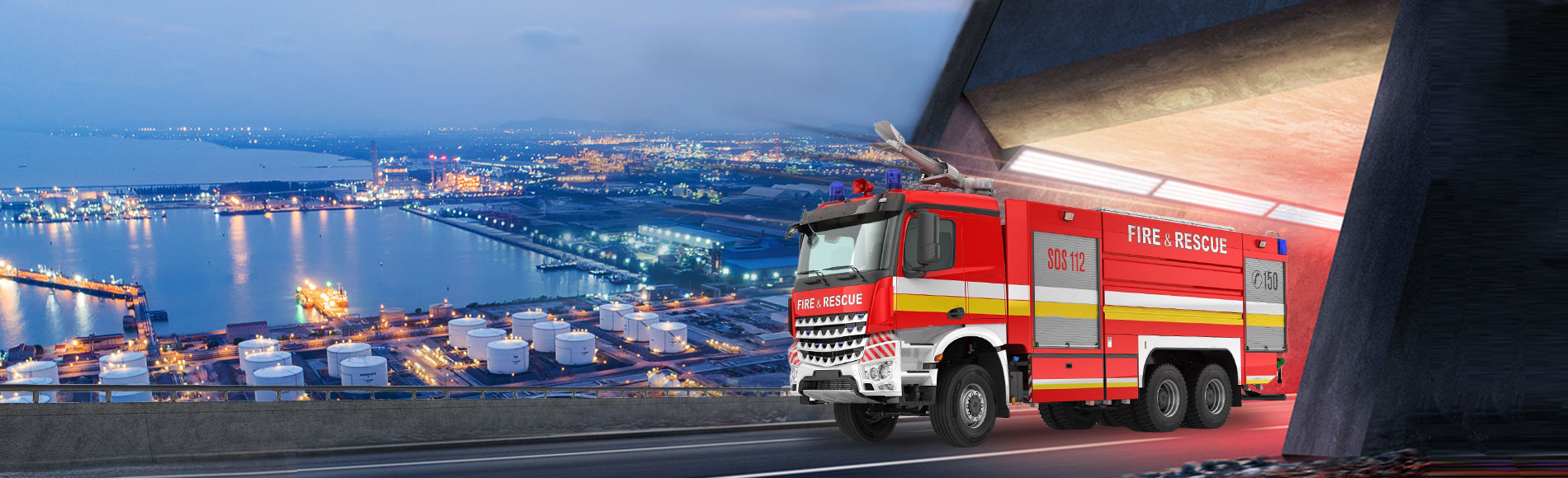
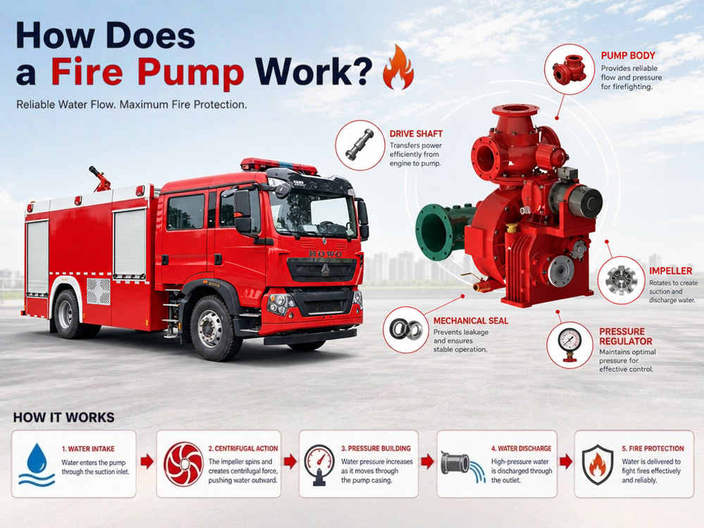
Ватрогасна пумпа је срце система за довод воде сваког ватрогасног возила. Било да реагује на пожар у објекту, индустријску ванредну ситуацију, инцидент на аеродрому или операцију на отвореном подручју, ватрогасна пумпана ватрогасном возилуодговорна је за довод воде под високим притиском до црева, ватрогасних монитора и система за пену.Њен центрифугални дизајн радног кола и систем са погоном преко PTO-а обезбеђују стабилан притисак и велики проток, директно повећавајући ефикасност гашења пожара за више од 40%, уз истовремено смањење времена реаговања за 3 пута. Може се назвати невидљивим чуваром ватрогасних операција и техничким темељем модерног реаговања у ванредним ситуацијама.
Сазнајте како функционише ватрогасна пумпа, укључујући њен принцип рада, главне компоненте, процес протока воде, стварање притиска и примене. Откријте како пумпе на ватрогасним возилима обезбеђују поуздано снабдевање водом за гашење пожара и како изабрати одговарајућу пумпу за ваше ватрогасно возило.Хајде да данас научимо о томе.
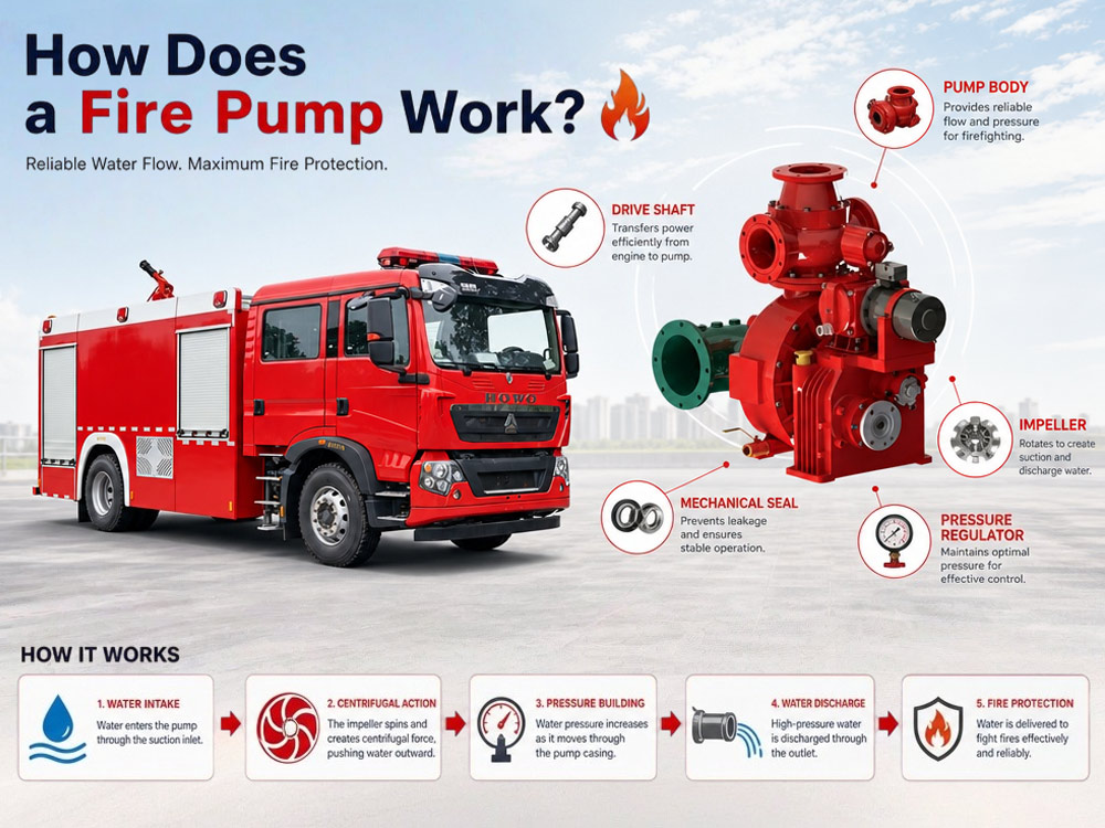
1. Радно коло:Ротирајућа компонента која увлачи воду и избацује је ка споља помоћу центрифугалне силе. Обично је направљена од бронзе, нерђајућег челика или ливеног гвожђа.
2. Кућиште пумпе:Кућиште које садржи радно коло и усмерава проток воде. Пројектовано је да претвара брзину у притисак.
3. Одвод снаге (PTO):Механичка веза која преноси снагу мотора са мењача возила на ватрогасну пумпу.
1. Снага се преноси са мотора преко PTO-а
Мотор возила покреће PTO, који је повезан са вратилом пумпе. Када руковалац активира PTO, снага мотора се преусмерава да великом брзином окреће радно коло пумпе.
2. Радно коло почиње да се окреће
Радно коло се окреће брзином од 1.500–2.500 RPM, увлачећи воду у пумпу кроз усисни отвор. Лопатице ротирајућег радног кола стварају зону ниског притиска у центру, увлачећи воду из уграђеног резервоара, хидранта или природног извора воде.
3. Центрифугална сила повећава притисак воде
Док се радно коло окреће, оно избацује воду ка споља помоћу центрифугалне силе. Брзина воде се повећава док се креће од центра ка спољној ивици радног кола. Кућиште пумпе затим претвара ту брзину у притисак, потискујући воду под високим притиском кроз излазни отвор.
4. Вода под високим притиском излази кроз излазни отвор
Вода под притиском (обично 0,8–1,2 MPa) излази кроз излазни отвор и доводи се до ватрогасних црева, ватрогасних монитора или система за дозирање пене за потребе гашења пожара.
Ватрогасна пумпа може да црпи воду из три извора:
Уграђени резервоар за воду:Примарни извор воде за почетни напад. Уобичајени капацитет: 2.000–12.000 литара. Обезбеђује тренутно снабдевање водом по доласку.
Ватрогасни хидрант:Повезан преко доводних црева. Обезбеђује непрекидно снабдевање водом за дуже операције. Притисак из хидранта помаже пумпи да одржи проток.
Природни извор воде (усисавање):Језера, реке, баре или базени. Пумпа користи систем за пуњење да уклони ваздух из усисног црева пре усисавања. Максимална теоријска висина подизања на нивоу мора: приближно 10 метара (33 стопе). Ефективна дубина усисавања: обично 7–8 метара.
Процес усисавања:
Повежите круто усисно црево са улазом пумпе
Потопите филтер најмање 2–3 стопе испод површине воде
Активирајте пуњач за уклањање ваздуха из црева и пумпе
Ствара се вакуум, атмосферски притисак потискује воду навише
Вода испуњава пумпу, а затим је центрифугална пумпа ставља под притисак
Усисни отвор:Место где вода улази у пумпу. Уобичајена величина: DN100–DN150. Опремљен је филтером како би спречио улазак нечистоћа.
Izlaz za pražnjenje:Mesto gde voda pod pritiskom izlazi. Tipična veličina: DN65–DN80 (standardni izlazi). Opremljen je ventilima za kontrolu protoka do creva ili monitora. Višestruki izlazi omogućavaju istovremenu upotrebu.
Rotor:Rotirajuća komponenta koja stvara protok vode. Pretvara mehaničku energiju u kinetičku energiju. Obično je izrađen od bronze (otporne na koroziju), nerđajućeg čelika (izdržljivog i dugotrajnog) ili livenog gvožđa (isplativog za standardne primene).
Kućište pumpe:Kućište koje usmerava protok vode. Projektovano je da pretvori brzinu u pritisak. Uobičajeni dizajni: spiralno kućište (spiralni oblik za nesmetan protok) i difuzorsko kućište (za veću efikasnost).
Sistem za usisavanje:Uklanja vazduh iz pumpe i usisnog creva pre usisavanja vode. Tipovi uključuju:
Vakuumski usisivač:Rotacioni lopatični ili klipni dizajn. Brz i efikasan. Najčešći u modernim vatrogasnim vozilima.
Izduvni usisivač:Koristi izduvne gasove motora za stvaranje vakuuma. Jednostavan, ali manje efikasan.
Električni usisivač:Pokreće ga motor. Može da izvrši usisavanje bez rotacije pumpe. Štiti mehanički zaptivač od oštećenja usled rada na suvo.
Ventil za rasterećenje pritiska:Sprečava prekomerni pritisak. Otvara se kada pritisak prekorači podešenu granicu. Štiti creva, pumpu i vatrogasce.
Regulator pritiska:Automatski održava podešeni pritisak. Podešava broj obrtaja motora kako bi nadoknadio promene protoka. Smanjuje opterećenje rukovaoca. Dostupan je u režimu pritiska (održava unapred podešeni pritisak) i režimu obrtaja (održava unapred podešenu brzinu motora).
PTO (odvod snage):Veza između motora i pumpe. Prenosi snagu motora za pogon pumpe. Vatrogasna vozila obično koriste sendvič PTO (postavljen između motora i menjača) za punu izlaznu snagu.
| Tip pumpe | Prednosti | Tipične primene |
|---|---|---|
| Jednostepena centrifugalna pumpa | Veliki protok, jednostavan dizajn, isplativa | Komunalna vatrogasna vozila |
| Dvostepena vatrogasna pumpa | Veći pritisak, prebacivi režimi | Gašenje požara u visokim zgradama, duga polaganja creva |
| Srednje postavljena vatrogasna pumpa | Bolja ravnoteža, stabilan rad | Standardna vatrogasna vozila |
| Pozadi postavljena vatrogasna pumpa | Lakše održavanje, bolje hlađenje | Aerodromska i industrijska vozila |
| Stavka poređenja | Vatrogasna pumpa | Standardna pumpa za vodu |
|---|---|---|
| Radni pritisak | Visok (0,8–2,5 MPa) | Niži (0,2–0,6 MPa) |
| Protok | Visok (1.200–6.000 L/min) | Umeren (500–2.000 L/min) |
| Kontinuirani rad | Da (projektovana za produženu upotrebu) | Zavisi od modela |
| Pogon preko PTO | Da | Obično ne |
| Usklađenost sa standardima za gašenje požara | Da (sertifikovana prema NFPA, EN, GB) | Ne |
| Oblasti primene | Gašenje požara i spasavanje | Industrijsko, poljoprivredno, kućno snabdevanje vodom |
| Primena | Preporučena pumpa | Razlog |
|---|---|---|
| Gradsko gašenje požara | Jednostepena (1.200–3.000 L/min) | Isplativa, dovoljna za većinu požara |
| Visoke zgrade | Dvostepena (2.000–4.000 L/min) | Veći pritisak za vertikalno podizanje |
| Petrohemijska postrojenja | Dvostepena (3.000–6.000 L/min) | Veliki protok i pritisak za industrijske požare |
| Spasavanje nakon avionskih nesreća na aerodromu | Montirana pozadi (4.000–6.000 L/min) | Veliki protok, lakše održavanje |
| Gašenje požara u divljim područjima | Jednostepena (1.000–2.000 L/min) | Lagana, prenosiva |
Vatrogasna pumpa stvara pritisak pomoću centrifugalne sile. Kada se radno kolo okreće, ono uvlači vodu u sredinu i izbacuje je napolje velikom brzinom. Kućište pumpe pretvara ovu vodu velike brzine u pritisak usporavanjem njenog kretanja.
Фактори који утичу на притисак:
Брзина радног кола:Бржа ротација = већи притисак. Брзина радног кола је директно пропорционална броју обртаја мотора.
Број обртаја мотора:Већа брзина мотора = брже радно коло = већи притисак. Оператери контролишу притисак подешавањем гаса мотора или коришћењем регулатора притиска.
Конструкција пумпе:Двостепене пумпе могу постићи већи притисак од једностепених пумпи коришћењем два радна кола повезана у серију.
Пречник цеви:Мањи пречник = већи притисак, али мањи проток. Већи пречник = мањи притисак, али већи проток. Оператер мора ускладити притисак и проток у складу са задатком гашења пожара.
Извор воде:Одговарајуће снабдевање водом је од суштинског значаја за одржавање притиска. Недовољно снабдевање доводи до пада притиска.
1. Пумпа не може да се напуни водом
Могући узроци: Цурење ваздуха у усисном цреву, зачепљено сито, уређај за пуњење не ради.
Решења: Проверите и затегните све спојеве усисног црева; очистите сито; прегледајте систем за пуњење (вакуум пумпу или електрични уређај за пуњење) и поправите ако је потребно.
2. Низак притисак воде
Могући узроци: Зачепљено сито, недовољан број обртаја мотора, истрошено радно коло, ваздух у систему.
Решења: Очистите сито; повећајте брзину мотора; прегледајте радно коло на хабање и замените га ако је потребно; проверите да ли постоје цурења ваздуха и поново напуните пумпу.
3. Кавитација
Формирање: Кавитација настаје када пумпа не добија довољно воде. Радно коло се окреће у мешавини воде и мехурића паре. Када се ти мехурићи уруше, стварају ударне таласе који оштећују радно коло и изазивају велике осцилације притиска.
Како избећи: Никада не покрећите пумпу брже него што довод воде може да обезбеди; пратите улазни притисак; смањите брзину пумпе ако је вакуум превисок; уверите се да сито није зачепљено.
4. Цурење воде
Ставке за проверу: Проверите све заптивке и дихтунге; прегледајте кућиште пумпе на пукотине; уверите се да су испусни вентили затворени; одмах замените истрошене заптивке.
5. Прегревање
Узроци: Рад пумпе без воде, недовољно хлађење, дуготрајан рад без протока воде.
Савети за одржавање: Никада не покрећите пумпу без воде; уверите се да су расхладни водови проходни; дозволите пумпи да се охлади између операција; редовно проверавајте термички растеретни вентил.
» VIII. Студија стварног случаја: Унапређење пумпе у градској ватрогасној служби
Позадина:
Градска ватрогасна служба са возним парком застарелих ватрогасних возила морала је да унапреди системе пумпи на три главна ватрогасна возила. Постојеће пумпе су имале потешкоће са одржавањем притиска током гашења пожара у високим зградама и често су захтевале поправке.
Изазов:
Нестабилан притисак на висинама изнад 50 метара
Споро усисавање из природних извора воде (време пуњења >45 секунди)
Низак проток при високом притиску
Чести кварови заптивки и хабање радног кола
Решење:
Ватрогасна пумпа CB10/60 (60 L/s @ 1.0 MPa)
Електрични вакуумски уређај за пуњење (побољшава брзину пуњења)
Аутоматски регулатор притиска (одржава стабилан притисак)
Побољшане заптивке и лежајеви пумпе
Нова усисна црева са већим филтерима
Резултати:
| Метрички показатељ | Пре | После |
|---|---|---|
| Притисак на висини од 50 m | 0.6 MPa | 0.9 MPa |
| Време усисавања | 45 секунди | 18 секунди |
| Проток при пуном притиску | 40 L/s | 55 L/s |
| Замене заптивки годишње | 4 | 0 |
Притисак је повећан за 25%, време усисавања смањено је за 35%, ефикасност гашења пожара је значајно побољшана, а трошкови одржавања су смањени за 60%. Одељење је пријавило брже време реаговања и поузданије пумпање током великих пожара.
1. Одредите потребан проток
| Примена | Препоручени проток |
|---|---|
| Комунално гашење пожара | 30–60 L/s |
| Индустријски паркови | 60–100 L/s |
| Спасавање при удесима на аеродромима | 100+ L/s |
| Гашење пожара у дивљим подручјима | 20–40 L/s |
| Високе зграде | 40–80 L/s |
2. Одредите потребан притисак
| Примена | Препоручени притисак |
|---|---|
| Комунално гашење пожара | 0.8–1.0 MPa |
| Industrijske zone | 1,0–1,2 MPa |
| Petrohemijske fabrike | 1,2–1,4 MPa |
| Spasavanje na aerodromu | 1,0–1,2 MPa |
| Zgrade visokih spratova | 1,5–2,5 MPa |
3. Razmotrite izvor vode
Snabdevanje hidranta: Jednostepena pumpa je dovoljna. Nije potrebno pripremanje.
Rezervoar na vozilu: Jednostepena ili dvostepena. Potrebno pripremanje za crpljenje.
Prirodna voda (crpljenje): Potrebna vakuumska priprema. Dvostepena pumpa za veće dizanje.
4. Veličina i konfiguracija vatrogasnog vozila
| Šasija | Preporučena pumpa |
|---|---|
| 4×2 | Jednostepena, 1.200–2.000 L/min |
| 4×4 | Jednostepena, 2.000–3.000 L/min |
| 6×4 | Dvostepena, 3.000–4.500 L/min |
| 8×4 | Dvostepena, 4.000–6.000 L/min |
P: Šta je vatrogasna pumpa?
O: Vatrogasna pumpa je centrifugalna pumpa koju pokreće motor vozila preko PTO sistema. Crpi vodu iz rezervoara na vozilu, hidranta ili prirodnih izvora, povećava pritisak vode okretanjem propelera i isporučuje vodu pod visokim pritiskom na creva ili vatrogasne monitor-e za gašenje požara.
P: Kako vatrogasna pumpa povećava pritisak vode?
O: Propeler se okreće velikom brzinom (1.500–2.500 RPM), uvlačeći vodu u centar i izbacujući je centrifugalnom silom. Kućište pumpe pretvara ovu vodu velike brzine u pritisak usporavajući je. Veća brzina propelera = veći pritisak.
P: Da li je vatrogasna pumpa ista kao standardna pumpa za vodu?
O: Ne. Vatrogasne pumpe su dizajnirane za veći pritisak (0,8–2,5 MPa), veće protoke (1.200–6.000 L/min) i kontinuirani rad u hitnim situacijama. Standardne pumpe rade pri nižem pritisku i nisu namenjene za gašenje požara ili PTO sisteme.
P: Šta pokreće pumpu vatrogasnog vozila?
O: Motor vatrogasnog vozila pokreće pumpu preko Power Take-Off (PTO) sistema. Kada operater uključi PTO, snaga motora se preusmerava na okretanje propelera pumpe. Nije potreban poseban motor.
P: Zašto vatrogasna pumpa treba pripremu?
O: Priprema uklanja vazduh iz pumpe i usisnog creva pre crpljenja iz jezera, reke ili bara. Centrifugalne pumpe ne mogu pomerati vodu ako je vazduh u sistemu. Priprema stvara vakuum, omogućavajući atmosferskom pritisku da gura vodu u pumpu.
P: Koja je razlika između jednostepene i dvostepene vatrogasne pumpe?
O: Jednostepena pumpa ima jedan radni točak i obezbeđuje veliki protok pri umerenom pritisku. Dvostepena pumpa ima dva radna točka u seriji i može da obezbedi veći pritisak. Dvostepene pumpe mogu da prelaze između režima zapremine (veliki protok) i režima pritiska (visok pritisak).
P: Može li vatrogasna pumpa da crpi vodu iz reke?
O: Da. Vatrogasna pumpa može da crpi vodu iz reka, jezera, bara i bazena kroz proces koji se naziva usisavanje. Usisni uređaj uklanja vazduh iz usisnog creva i pumpe, stvarajući vakuum. Atmosferski pritisak potiskuje vodu nagore u pumpu. Maksimalna praktična visina podizanja: približno 7–8 metara.
P: Šta uzrokuje kavitaciju vatrogasne pumpe?
O: Kavitacija nastaje kada pumpa ne dobija dovoljno vode. Radno kolo se okreće u mešavini vode i parnih mehurića. Kada se ti mehurići uruše, stvaraju udarne talase koji oštećuju radno kolo. Kavitaciju uzrokuje rad pumpe brže nego što dovod vode može da obezbedi, začepljena sita ili prevelika usisna visina.
P: Koliko često treba servisirati vatrogasnu pumpu?
O: Dnevne provere (buka, vibracije, curenja), nedeljna testiranja (usisni uređaj, regulator pritiska), mesečni pregledi (radno kolo, ležajevi, rasteretni ventil), godišnja ispitivanja punog protoka i hidrostatičko ispitivanje pritiska. Redovno održavanje sprečava neočekivane kvarove tokom hitnih slučajeva.
P: Kako da izaberem odgovarajuću vatrogasnu pumpu za svoje vatrogasno vozilo?
O: Uzmite u obzir potreban protok (na osnovu rizika od požara), zahteve za pritiskom (na osnovu visine objekata), izvor vode (hidrant, rezervoar ili prirodni izvor), šasiju vatrogasnog vozila (4×2, 4×4, 6×4, 8×4), marku pumpe i pouzdanost, kao i podršku za održavanje i servisiranje. Pumpa mora odgovarati snazi motora vozila i konfiguraciji PTO sistema.
Vatrogasne pumpe koriste centrifugalnu silu za povećanje pritiska vode. Radno kolo uvlači vodu i izbacuje je ka spolja, pretvarajući brzinu u pritisak.
Većina pumpi vatrogasnih vozila pokreće se preko PTO sistema (Power Take-Off). Snaga motora se preusmerava na pumpu, nije potreban zaseban motor.
Voda može dolaziti iz ugrađenih rezervoara, hidranata ili otvorenih izvora vode. Usisavanje iz prirodnih izvora zahteva usisni uređaj za uklanjanje vazduha iz usisnog creva.
Sistemi za usisavanje uklanjaju vazduh pre crpljenja iz prirodnih izvora vode. Vakuumski usisni uređaji su najčešći, dok električni usisni uređaji pružaju zaštitu za mehaničke zaptivke.
Performanse pumpe zavise od protoka, pritiska, veličine radnog kola i snage motora. Usklađivanje pumpe sa zadatkom gašenja požara je od ključnog značaja.
Pravilno održavanje (dnevno, nedeljno, mesečno, godišnje) poboljšava pouzdanost i radni vek. Redovno testiranje sprečava neočekivane kvarove tokom hitnih slučajeva.
Razumevanje rada pumpe pomaže kupcima da izaberu odgovarajuće specifikacije za svoje vatrogasno vozilo. Pumpa mora odgovarati šasiji, PTO sistemu i zahtevima za gašenje požara.


Можда ћете бити заинтересовани за следеће информације
Ватрогасна пумпа је срце система за довод воде сваког ватрогасног возила. Било да реагује на пожар у објекту, индустријску ванредну ситуацију, инцидент на аеродрому или операцију на отвореном подручју, ватрогасна пумпана ватрогасном возилуодговорна је за довод воде под високим притиском до црева, ватрогасних монитора и система за пену.Њен центрифугални дизајн радног кола и систем са погоном преко PTO-а обезбеђују стабилан притисак и велики проток, директно повећавајући ефикасност гашења пожара за више од 40%, уз истовремено смањење времена реаговања за 3 пута. Може се назвати невидљивим чуваром ватрогасних операција и техничким темељем модерног реаговања у ванредним ситуацијама. Сазнајте како функционише ватрогасна пумпа, укључујући њен принцип рада, главне компоненте, процес протока воде, стварање притиска и примене. Откријте како пумпе на ватрогасним возилима обезбеђују поуздано снабдевање водом за гашење пожара и како изабрати одговарајућу пумпу за ваше ватрогасно возило.Хајде да данас научимо о томе. » I. Прво, треба да знамо три кључне компоненте система ватрогасне пумпе: 1. Радно коло:Ротирајућа компонента која увлачи воду и избацује је ка споља помоћу центрифугалне силе. Обично је направљена од бронзе, нерђајућег челика или ливеног гвожђа. 2. Кућиште пумпе:Кућиште које садржи радно коло и усмерава проток воде. Пројектовано је да претвара брзину у притисак. 3. Одвод снаге (PTO):Механичка веза која преноси снагу мотора са мењача возила на ватрогасну пумпу. » II. Након упознавања са кључним компонентама, основни принцип рада ватрогасне пумпе је следећи: 1. Снага се преноси са мотора преко PTO-а Мотор возила покреће PTO, који је повезан са вратилом пумпе. Када руковалац активира PTO, снага мотора се преусмерава да великом брзином окреће радно коло пумпе. 2. Радно коло почиње да се окреће Радно коло се окреће брзином од 1.500–2.500 RPM, увлачећи воду у пумпу кроз усисни отвор. Лопатице ротирајућег радног кола стварају зону ниског притиска у центру, увлачећи воду из уграђеног резервоара, хидранта или природног извора воде. 3. Центрифугална сила повећава притисак воде Док се радно коло окреће, оно избацује воду ка споља помоћу центрифугалне силе. Брзина воде се повећава док се креће од центра ка спољној ивици радног кола. Кућиште пумпе затим претвара ту брзину у притисак, потискујући воду под високим притиском кроз излазни отвор. 4. Вода под високим притиском излази кроз излазни отвор Вода под притиском (обично 0,8–1,2 MPa) излази кроз излазни отвор и доводи се до ватрогасних црева, ватрогасних монитора или система за дозирање пене за потребе гашења пожара. » III. Одакле ватрогасна пумпа добија воду? Ватрогасна пумпа може да црпи воду из три извора: Уграђени резервоар за воду:Примарни извор воде за почетни напад. Уобичајени капацитет: 2.000–12.000 литара. Обезбеђује тренутно снабдевање водом по доласку. Ватрогасни хидрант:Повезан преко доводних црева. Обезбеђује непрекидно снабдевање водом за дуже операције. Притисак из хидранта помаже пумпи да о...
Детаљи
Систем пумпе и распршивања ватрогасног возила је језгро операција гашења пожара. Он делује као „моћна рука“ ватрогасног возила. Претварањем снаге мотора у притисак (у распону од 0,8 до 1,4 MPa), он доставља средства за гашење на висине до 85 метара — било да је реч о пожару у високој згради у густом градском центру или пожару резервоара за петрохемијско складиштење у индустријској зони, ватрогасно возилосе ослања на овај систем за постизање ефикасног гашења пожара. Који фактори утичу на висину распршивања ватрогасног возила и како притисак пумпе, проток и ватрогасни монитор заједно функционишу? Ово су питања која занимају многе купце. Хајде да то данас научимо. » I. Три кључне компоненте које одређују висину распршивања 1. Систем ватрогасне пумпе: Срце ватрогасног возила. Центрифугална пумпа покретана преко PTO система. Уобичајени нивои притиска: 0,8 MPa, 1,0 MPa, 1,2 MPa, 1,4 MPa. Протоци од 2.000 до више од 5.000 L/min. 2. Ватрогасни монитор: Последња компонента пре него што средство за гашење напусти возило. Доступан у варијантама монитора за воду, монитора за пену и двонаменског монитора. PL-серија (PL48) са протоком до 4.000 L/min и висином распршивања већом од 70 метара. 3. Систем довода: Цеви, црева и млазнице које преносе средство за гашење од пумпе до монитора. Пречник црева, дужина и тип млазнице утичу на коначну висину распршивања. » II. Кључни фактори који одређују висину распршивања 1.1. Притисак пумпе Притисак пумпе ватрогасног возила је сила коју ствара ватрогасна пумпа како би потиснула средство за гашење кроз црева и избацила га из млазница или монитора. Он је главни покретач и протока и даљине распршивања. Већи притисак ствара већу брзину на излазу монитора, директно повећавајући висину распршивања. Однос је одређен формулом H ≈ P/(ρg), где свако повећање од 0,1 MPa додаје приближно 10 метара теоријске висине — али стварни губици то смањују. У практичним операцијама гашења пожара примењују се следећи опсези: Притисак пумпе Типична висина распршивања 0,8 MPa 35–45 метара 1,0 MPa 45–55 метара 1,2 MPa 55–70 метара 1,4 MPa 70–85 метара 1.2. Како функционише ватрогасна пумпа: Пумпа је обично центрифугална пумпа коју покреће мотор возила преко прикључка за одузимање снаге (PTO). Како се радно коло окреће, оно увлачи средство за гашење и избацује га ка споља центрифугалном силом, стварајући притисак који га потискује кроз излазни систем. Називни притисак у односу на радни притисак: Појам Дефиниција Називни притисак Максимални притисак који пумпа може непрекидно да одржава у условима пројектовања Радни притисак Стварни притисак који се користи током гашења пожара, обично нижи од називног притиска како би постојала резерва 2. Проток (L/min) Одговарајући проток је једнако важан као и притисак. Висок притисак са малим протоком не може да испоручи довољно средства за гашење како би се пожар угасио. Систем пумпе мора истовремено да одржава и притисак и проток. Однос протока и висине распршивања: 2.000 L/min → ефикасно за градске пожаре 3...
Детаљи
Систем пумпе ватрогасног возила је поуздан онолико колико су поуздане његове компоненте. Од извлачења воде из извора до њеног испуштања под високим притиском, сваки додатак има кључну улогу. Овај водич обухвата ватрогасно возило пет кључних категорија додатне опреме: уређаји за примарно вакуумско пуњење, куглични вентили, глобус вентили, дозатори пене и хидраулични контролни системи. Разумевање ових компоненти помаже ватрогасцима да одржавају своју опрему и изаберу одговарајуће додатке за специфичне примене. I. Серија уређаја за примарно пуњење (вакуумски уређаји за пуњење) Уређаји за примарно пуњење су неопходни за извлачење воде из језера, река или других статичких извора када хидрант није доступан. Они уклањају ваздух из пумпе и усисног црева, омогућавајући атмосферском притиску да потисне воду у пумпу. Преглед производа Производ Максимални вакуум Напон Снага Одговарајућа величина пумпе уређај за примарно пуњење са 2 клипа >85kPa 24V - Испод 100 L/s електрични уређај за примарно пуњење са 2 клипа >85kPa 24V 2.1KW Испод 100 L/s уређај за примарно пуњење са 4 клипа >85kPa 24V - Изнад 100 L/s електрични уређај за примарно пуњење са 4 клипа >85kPa 24V 2.1KW Изнад 100 L/s Кључна карактеристика: електрични уређаји за примарно пуњење Електрични уређаји за примарно пуњење нуде значајну предност — могу да напуне пумпу без окретања пумпе. Ово штити механичку заптивку од оштећења услед рада на суво. Док стандардни уређај за примарно пуњење захтева да се пумпа окреће, електрична верзија ради независно, продужавајући век трајања заптивке. II. Серија кугличних вентила (контрола протока) Куглични вентили контролишу проток воде кроз црева и излазне отворе. Дизајнирани су за брзо укључивање/искључивање једноставним окретањем од 90°. Куглични вентили од нерђајућег челика Модел Материјал Називни притисак Navoj Rad FQS65/2.5 Telo i kugla: nerđajući čelik 304; Zaptivka: PTFE 2.5 MPa G2-1/2" Ručni točak / Poluga FQS80/2.5 Telo i kugla: nerđajući čelik 304; Zaptivka: PTFE 2.5 MPa G3" Ručni točak / Poluga Kuglasti ventili od legure aluminijuma (manja težina) Model Materijal Nazivni pritisak Navoj Rad FQS65/2.5 Telo: A356.2; Kugla: 304; Zaptivka: PTFE 2.5 MPa G2.5" Ručni točak / Poluga FQS80/1.6 Telo: A356.2; Kugla: 304; Zaptivka: PTFE 1.6 MPa G3" Ručni točak / Poluga FQS65/2.5 kvadratni Telo: A356.2; Kugla: 304; Zaptivka: PTFE 2.5 MPa - Pneumatski / Poluga Ⅲ. Serija globus ventila (regulacija pritiska i protoka) Za razliku od kuglastih ventila koji su namenjeni za rad uključeno/isključeno, globus ventili omogućavaju preciznu kontrolu protoka i pritiska. Idealni su za situacije gde je potrebno postepeno podešavanje. Model Materijal Nazivni pritisak Navoj Rad DN65/2.5 Kućište: A356.2; Vreteno: H62; Zaptivka: NBR 2.5 MPa G2.5" Ručni točak DN80/2.5 Kućište: A356.2; Vreteno: H62; Zaptivka: NBR 2.5 MPa G3" Ručni točak Kada koristiti globusni ventil Koristite globusne ventile na izlaznim tačkama gde je potrebna fina kontrola pritiska, kao...
Детаљи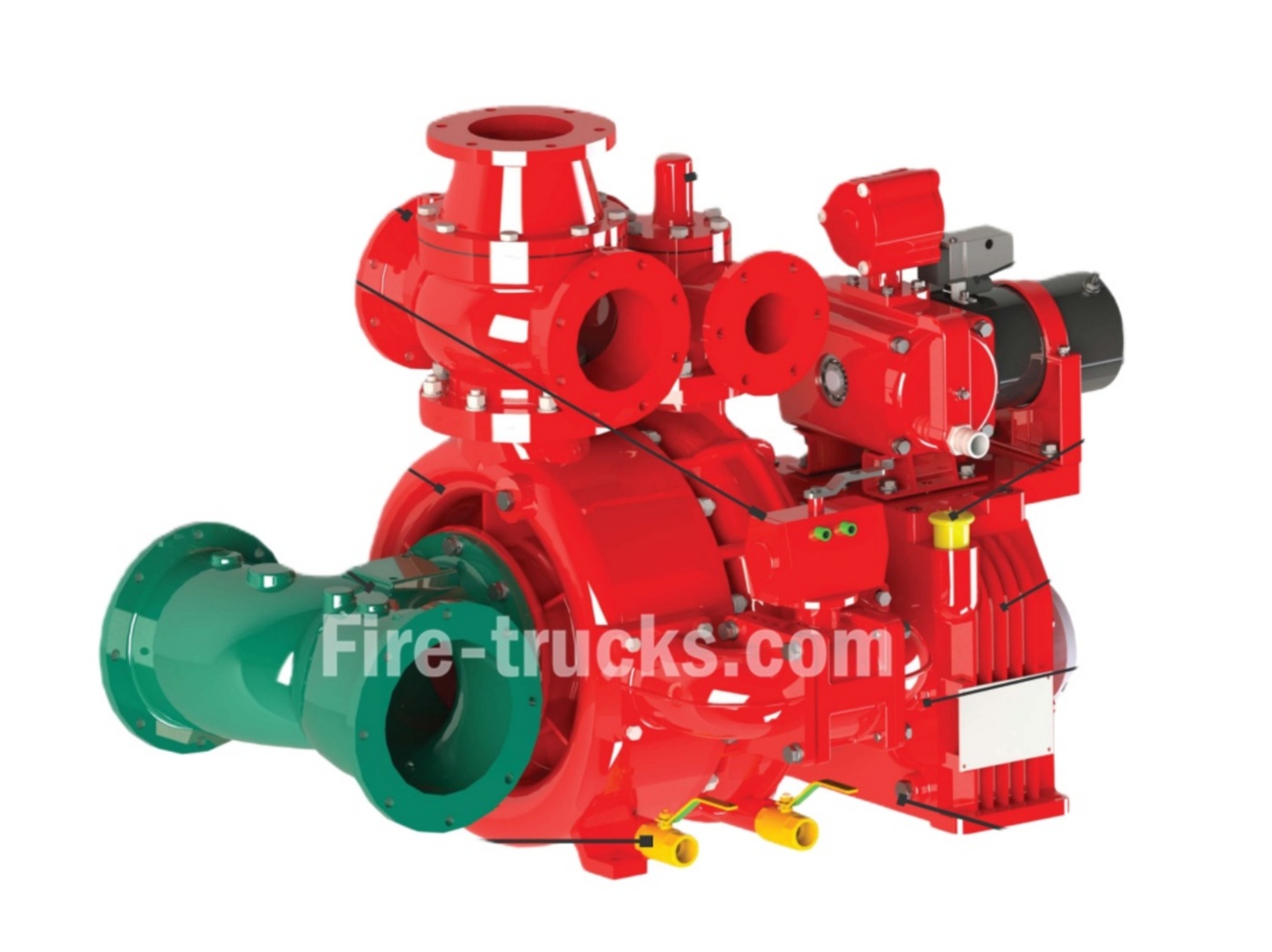
Као професионални сионгџен произвођач ватрогасних пумпи у Кини, Камиони Пауерстар поседује сопствену серију производа бренда „Xiongzhen“, укључујући ватрогасне пумпе ниског притиска, ватрогасне пумпе средњег и ниског притиска и ватрогасне пумпе високог и ниског притиска монтиране на возила, као и пратећу опрему као што су монитори за пожар и дозатори пене. Њене ватрогасне пумпе користе нове материјале као што су легуре алуминијума и нерђајући челик и опремљене су електромагнетним уређајем за аутоматско искључивање квачила и неповратним вентилом, што им даје одличне перформансе, једноставно руковање и практично одржавање. Производи компаније су прошли типска испитивања од стране Националног центра за надзор и инспекцију квалитета ватрогасне опреме, CCC сертификат и ISO9001 сертификат система управљања квалитетом. Противпожарне пумпе Xiongzhen углавном укључују следеће моделе: CB10/20-XZ, ЦБ10/30-XZ , CB10/40-XZ, ЦБ10/60-XZ , CB10/80-XZ, CB10/100-XZ, CB20.10/15.30-XZ, CB20.10/20.40-XZ, CB20.10/30.60-XZ, итд. ВАТРОГАСНА ПУМПА CB10/20-XZ за ватрогасна возила ВАТРОГАСНЕ ПУМПЕ CB10/30-XZ за ватрогасна возила Ватрогасне пумпе модела CB10/40-XZ за ватрогасна возила Кина Ватрогасне пумпе модела CB10-60 за ватрогасна возила Ватрогасне пумпе за хитне случајеве CB10/80-XZ за ватрогасна возила Ватрогасне пумпе CB10/100-XZ за ватрогасно возило Спецификација система ватрогасних пумпи xiongzhen CB10/100-XZ Произвођачи ватрогасних пумпи серије Xiongzhen CB Спецификације ватрогасних пумпи CB10/150 Систем противпожарних пумпи CB10/160-XZ фабрика Xiongzhen Спецификације ватрогасних пумпи за хитне случајеве CB10/170-XZ Компанија Powerstar Trucks се може похвалити снажним техничким могућностима, поседује четири патента и користи напредну производну опрему као што су CAD цртање и CNC машински алати како би се осигурала висока стопа квалификације производа и задовољство купаца. Њени производи су првенствено намењени фабрикама за модификацију ватрогасних возила и ватрогасним бригадама. Спецификација детаља и спецификације ватрогасне пумпе CB20.10 20.40 Ватрогасна пумпа CB20.10 30.60-XZ од фабрике Xiongzhen Ватрогасна пумпа серије CB20/15-XZ Ватрогасна пумпа за хитне случајеве серије CB20/20-XZ Инсталација ватрогасне пумпе CB20 25 детаља Ево распореда одржавања за ваш XIONGZHEN ватрогасне пумпе , категорисано по недељи, месецу, кварталу и години ради лакшег сналажења: 01, Дневна инспекција ватрогасне пумпе Powersar: Проверите притисак покретања и заустављања и фреквенцију пумпе за стабилизацију притиска. Проверите стартну снагу батерије ватрогасне пумпе са дизел мотором. Проверите да ли су вентили за контролу извора воде и склопови алармних вентила оштећени. 02, Powersar ватрогасна пумпа Недељна инспекција: Тестирајте аутоматски старт мотора противпожарне пумпе. Проверите ниво горива у ватрогасној пумпи дизел мотора. 03, Powersar ватрогасна пумпа Месечна инспекција: Тестирајте ручни старт мотора ватрогасна пумпа и ватрогасну пумпу са дизел мотором. Проверите ниво воде у р...
Детаљи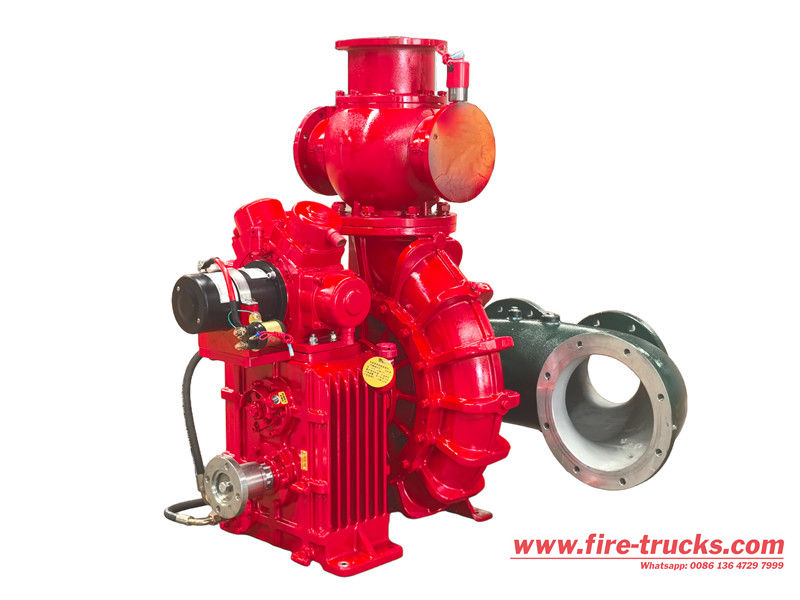
Противпожарна пумпа са пеном CB10/140 је често коришћени систем за снабдевање водом за гашење пожара, монтиран на возило или стационаран, са номиналним притиском од 1,0 MPa и номиналним протоком од 140 L/s, који задовољава основне потребе за снабдевањем водом противпожарних система. Тело пумпе и импелер су направљени од висококвалитетних, отпорних на хабање материјала, нудећи отпорност на корозију и висок притисак. Има дизајн са двоструким улазом за брзу промену извора воде и покреће га високоефикасан мотор или дизел мотор, постижући време одзива при покретању од 30 секунди или мање. Захваљујући свом компактном дизајну, лаком одржавању и поузданом раду, Пумпа за гашење пожара пеном CB10/140 је витални део опреме за обезбеђивање ефикасног снабдевања водом за ватрогасне операције. Ватрогасна пумпа ниског притиска CB10/140-XZ, монтирана на камион, има једностепену центрифугалну структуру са кућиштем од легуре алуминијума и месинганим импелером. Користи електрични систем за пуњење водом са четири клипа и електричним прекидачем. Опционална пумпа за пену CB10/20 користи пнеуматски механизам за одвајање. Овај производ нуди одличне перформансе, компактну структуру, једноставан рад и лако одржавање. Ватрогасна пумпа CB10/140-XZ је једностепена центрифугална водена пумпа која се користи у ватрогасним возилима, а карактерише је двоклипни уређај за пуњење који се аутоматски укључује и искључује. Дизајнирана је за високе перформансе са компактном структуром, једноставним руковањем и практичним одржавањем. Кључне спецификације укључују проток од 140 л/с и излазни притисак од 1,0 MPa при номиналној брзини од 2600 о/мин. » . Принцип рада пумпе за гашење пожара пеном CB10/140 ● Унос воде и концентрата пене: Вода се црпи из извора, а концентрат пене се црпи из резервоара за складиштење. ● Пропорционирање: Дозирач меша концентрат пене са водом у унапред одређеном односу. ● Притисак: Пумпа притиска смешу, повећавајући њену брзину и притисак. ● Отпуст: Раствор пене под притиском се потискује кроз црево за испуштање до млазнице, где се испушта у ватру. ● Сузбијање пожара: Пена прекрива извор горива, одвајајући га од кисеоника и гасећи пожар. » . Детаљан увод у пумпу за гашење пожара пеном CB10/140 1. Врхунски структурни дизајн, стабилне и поуздане перформансе: ● The Ватрогасна пумпа CB10/140 Има једностепени центрифугални дизајн и направљен је од легуре алуминијума високе чврстоће, нудећи предности као што су мала тежина, отпорност на корозију и отпорност на високе температуре. ● Унутрашња структура пумпе је прецизно обрађена, што обезбеђује гладак проток и одличне хидрауличне перформансе. Механичко заптивање спречава цурење и обезбеђује дугорочну радну поузданост. ● Ова ватрогасна пумпа се може похвалити снажним усисним и пражњеним капацитетом, што је чини погодном за разна средња и велика ватрогасна возила и опрему за гашење пожара у хитним случајевима. 2. Једноставно руковање и висока прилагодљивост: ♦ Пумпа за гашење пожара пеном CB10/140 може се директно повезати...
Детаљи
Molimo vas da čitate dalje, ostanite obavešteni, pretplatite se i rado ćemo čuti vaše mišljenje.

 ИПв6 мрежа подржана

 српски
 English
 français
 Deutsch
 русский
 italiano
 español
 português
 Nederlands
 العربية
 日本語
日本語 한국의
한국의 Türkçe
 Melayu
 ไทย
ไทย Tiếng Việt
 Indonesia
  中文
中文 қазақ
қазақ Filipino
 မြန်မာ